ZHCSV99C February 1997 – October 2024 XTR105
PRODUCTION DATA
- 1
- 1 特性
- 2 應(yīng)用
- 3 說明
- 4 Pin Configuration and Functions
- 5 Specifications
- 6 Detailed Description
- 7 Application and Implementation
- 8 Device and Documentation Support
- 9 Revision History
- 10Mechanical, Packaging, and Orderable Information
封裝選項(xiàng)
機(jī)械數(shù)據(jù) (封裝 | 引腳)
散熱焊盤機(jī)械數(shù)據(jù) (封裝 | 引腳)
訂購信息
7.1.4 Radio Frequency Interference
The long wire lengths of current loops invite radio frequency (RF) interference. RF can be rectified by the sensitive input circuitry of the XTR105, causing errors. This generally appears as an unstable output current that varies with the position of loop supply or input wiring.
If the RTD sensor is remotely located, the interference can enter at the input terminals. For integrated transmitter assemblies with short connections to the sensor, the interference more likely comes from the current loop connections.
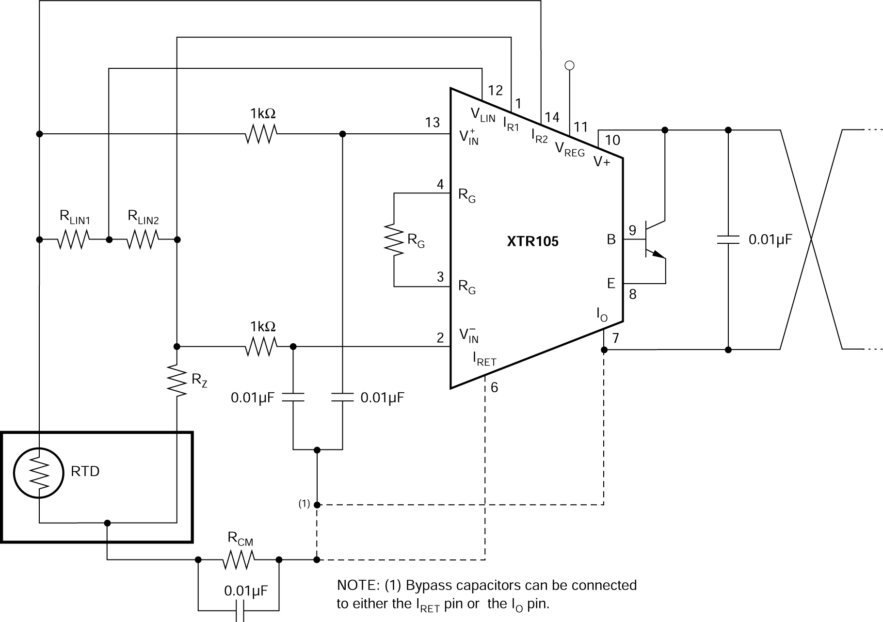
Bypass capacitors on the input reduce or eliminate this input interference. Connect these bypass capacitors to the IRET terminal (see Figure 7-4). Although the dc voltage at the IRET terminal is not equal to 0V (at the loop supply, VPS), this circuit point can be considered the transmitter ground. The 0.01μF capacitor connected between V+ and IO can help minimize output interference.
 Figure 7-4 Input Bypassing Technique With
Linearization