SLVAG23 May 2025 DRV8162
While similar to other robots currently in factory and service roles, humanoid robots are designed to mimic human movement with a high number of degrees of freedom (DOF) and fast response time (in milliseconds) to the surrounding environment. This creates a challenge for robotic system engineers as they solve key power-related design challenges in the many motors throughout these robots, as shown in Figure 1.
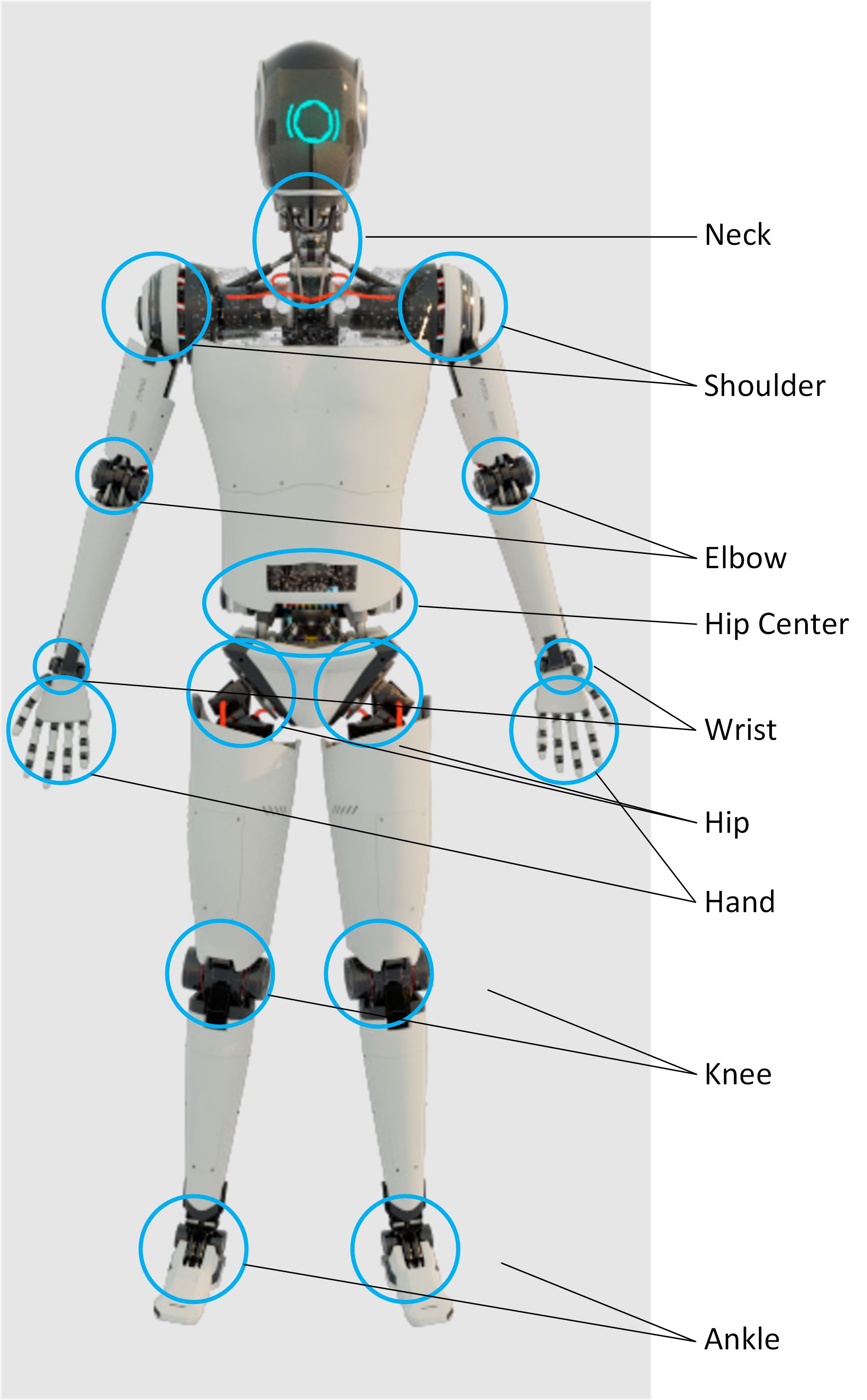 Figure 1 Showing Locations of DOF in Humanoid Robots
The DOF shown in Figure 1 have different power requirements based on the amount of load the motor needs to move the power level, which typically varies between 10W to 4kW with the majority of the drives between 10W and 1.5kW.
The typical power requirements can be categorized into the following options:
- 10W to 100W: Wrist and hand
- 100W to 300W: Ankle, shoulder, neck
- 1kW to 1.9kW: Elbow 1.5kW
- 2.5kW to 4kW: Knee, hip, hip center
These categories have different requirements for motor size and thermal performance that need to be considered when selecting components. Motor type is another consideration with selection based on power level and efficiency requirements.
For example, when designing with permanent magnet synchronous motors (PMSM), engineers can choose from trapezoidal or sinusoidal control topologies. Typically sinusoidal control is selected due to how the winding and control algorithm affects how precise the motor can be controlled.
The humanoid battery is typically built to work within the SELV voltage range, which is below 60V. This means that the components need to be operational up to 60V, there is even a preference to be to be operational up to 100V to reduce effects of potential noise in the system for the FETs, and gate drivers.
Using higher switching frequencies to reduce torque ripple effects of the drive enables more precise torque control for the motion controller, helping improve performance of the drive. To enable this, higher switching frequencies in high-performance MosFETs or GaN FETs are required to implement the drive and therefore help increase motor efficiency. GaN FETs have lower switching energy due to low FET capacitance and no body diode. This gives them the advantage of lower switching losses at higher switching frequencies. Sophisticated algorithms can also help reduce the switching requirements and losses of the motors FETs.
High-power density in motor drives is an important consideration due to the temperature limitations of robots where the exterior of the robot is not allowed to be higher than 55°C, as this temperature can cause full-thickness skin burn in 30 seconds. For a robot working in close proximity to humans, contact such as this can happen very quickly. With the size and weight requirements of humanoid robots, the temperature management design cannot accommodate fans or liquids. Since active cooling is not an option for thermal management, that means the bot must produce less power losses to maintain low temperature.
Functional safety is another crucial consideration when designing humanoid robots. Currently there are no standards that define the functional safety requirements of humanoid robots, though there are standards for cobots and industrial robots. However, there are study groups around the world that are analyzing humanoid robots to develop safety requirements in the future for them. Until safety requirements are defined, humanoid designers must conduct due diligence of current system designs to minimize redesign efforts in the future. Right now, taking note of the ISO13482, ISO10218 and the ISO 3691-4 can give some insight to what to expect in the future. This topic is a generic topic which is the same for all motor drive classes and is discussed in a separate chapter.
10W to 100W: Wrist and Hand
The wrist and hand system of a humanoid robot typically requires eight or more motors per hand to match the key movements of the hand and wrist. With this large number of motors in such a small space, size is a premium. Using higher levels of integration in the ICs on the board can help reduce the size of the total design.
During design, considerationis needed for how to split this system into blocks that benefit from integration and size optimize the design the best. A typical approach for the motor drive is to integrate FETs, gate driver, and current sensing for all three phases in one device. This device connects to a motor controller which can receive the signals from the integrated motor and communicate with the robot controller.
TI has a large portfolio of motor drives and integrated GaN half-bridges. Many of these devices offer the high level of integration which fits and is required to enable designers to build these highly compact systems.
Silicon FET: Gate Driver Integrated
High levels of device integration and potential space savings are key design considerations when selecting BLDC motor drivers. DC bus voltage for the wrist to hand vary from the other portions of humanoid robots. Voltage rail can range from 24V to 48V depending on the implementation. The recommendation when selecting a BLDC driver is to choose one that has an absolute maximum voltage that is 1.5 to two times the operating voltage. To accommodate for designs that require 24V, the DRV8316C is the recommended device to use. DRV8316C is a 40V, 8A peak rated 3-phase motor driver that integrates the FETs and three CSAs. The RDS(ON) high side plus low side is 95mΩ, making it robust to higher current and manage thermals in the system appropriately. This device has an integrated buck converter and LDO and SPI and hardware interface available in a 7x5mm QFN package. For 36 to 48V operation, DRV8376 is a new addition to the integrated FET BLDC family. It is a 70V, 4A peak rated 3-phase motor driver with integrated FETs and 3 CSAs. The RDS(ON) high side plus low side is 400mΩ. DRV8376 has adjustable output voltage slew rate at 1.1V/ns reducing the switching losses. For low audible noise and simple motor control, DRV8376 has ultra-low deadtime less than 200ns and propagation delay less than 100ns. SPI and hardware interfaces are available for the device in a small 6x5mm QFN package. For integrated FET motor drivers, thermal calculators are available to determine the power capability of the device based on the system requirements. Typical operation for DRV8316C is 80W and for DRV8376, 50W. These values can vary for specific system implementation.
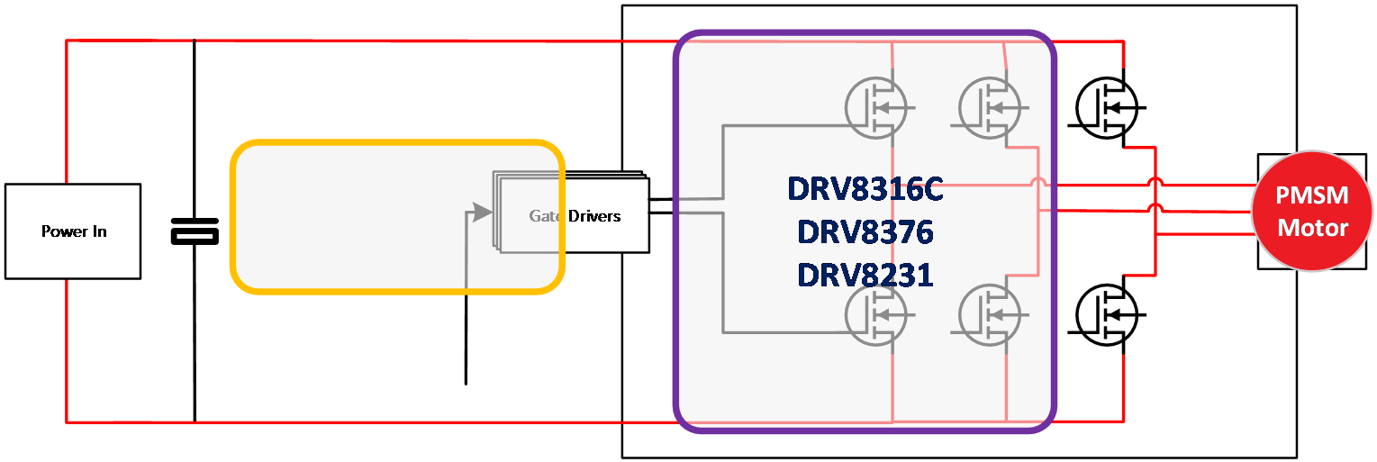 Figure 2 Gate Driver Block Diagram
100W to 300W: Ankle, Shoulder, Neck
Due to the location of these systems more space is available, which leaves more options of how to design the drives in this category.
When designing these drives the customer needs to pick motor drives which can both achieve the power requirement and the size constraint. Here both solutions using gate drivers with integrated FETs and options with external FETs can be implemented as the size here is not as critical, however thermal considerations must be made to verify the overall temperature of the robot is kept low enough.
Silicon FET: Gate Driver
With higher power needed for ankles, shoulders, and neck, a gate driver is typically used when designing. This gives engineers flexibility to swap FETs for even higher power requirements while keeping the same gate driver design. For this power and higher 48V rail is used for these joints. DRV8300, DRV835xF, and DRV8162 are recommended devices for this voltage and power level. DRV8300 is a simple 100V, 3-phase gate driver with minimal integration. The key use case for this device is for cost sensitive and space constrained systems. There are many variants of package from TSSOP to QFN including a bootstrap diode or optionally implementing externally. DRV8353F is a high integration 100V capable device with a Functional Safety Quality Managed Certification and three integrated CSAs. In many robotics environments the need for safety is key when interacting with humans. DRV8353F has documentation to aid IEC 61800-5-2 functional safety system design. DRV8162 is a smart single-half bridge gate driver that implements the same safety considerations as the DRV8353F. Read more about the DRV8162 for robotics applications in Cobots to humanoids: Driving system efficiency and safety into higher-power robots
GaN FET: Power Stage
GaN devices are also being used increasingly in humanoid robots to meet thermal requirements and space constraints. The LMG2100R044 is a 100V, 4.4m? half-bridge and driver with integrated bootstrap diode. This device comes in a 4.5 × 5.5mm QFN package and can power a 3-phase inverter up to 16A without a heat sink. See GaN 3-Phase Inverter design guide for more information.
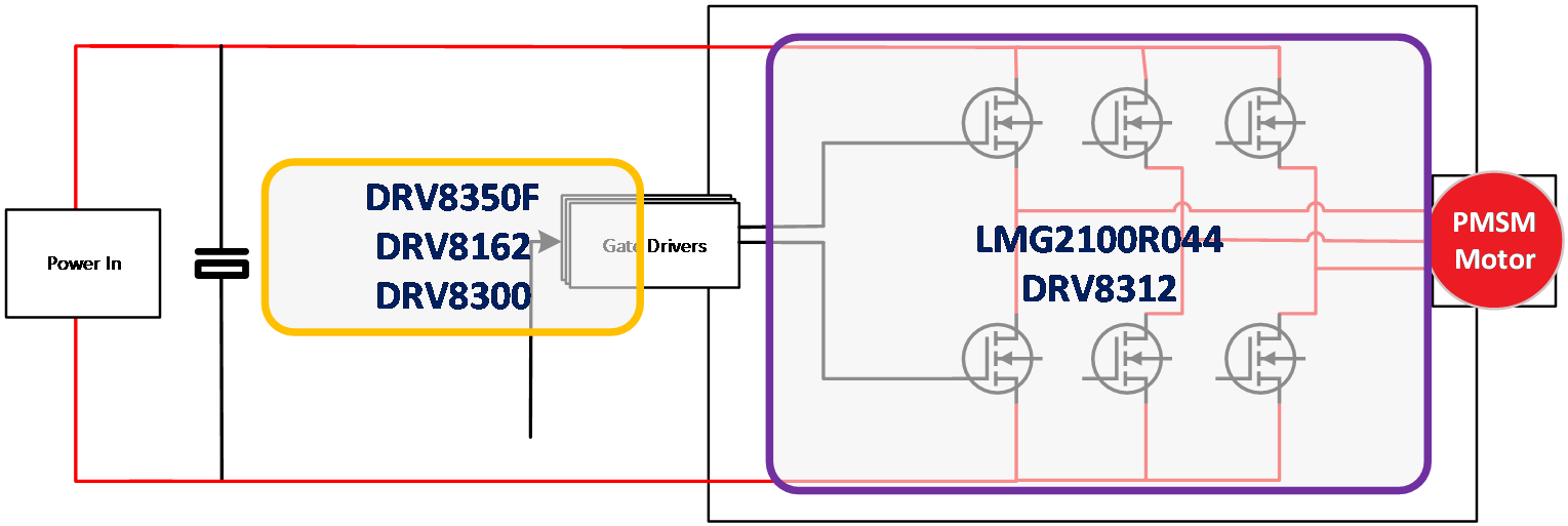 Figure 3 Gate Driver Block Diagram
1kW to 1.9kW: Elbow
On this category both functional safety and higher power is required. Here the thermal performance and efficiency of the drive is critical due to the higher mechanical weight of the joints, so the designer must develop a design with high power density.
One part of achieving higher efficiency is to improve the torque and current ripple of the drive by increasing the used frequency of the motor driver.
Options such as GaN FETs can be considered because the FETs have lower losses and smaller sized design.
Figure 4 shows the power stage block diagram.
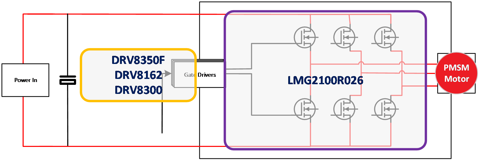 Figure 4 Power Stage Block Diagram
BLDC: Gate Driver
See 100W to 300W: Ankle, Shoulder, Neck for more information.
GaN FET: Power Stage
For the elbow joints the LMG2100R026 provides power density while minimizing losses to meet thermal requirements. The LMG2100R026 is available in a 4.5 × 7mm QFN package including gate driver, bootstrap diode, and 2.6m? GaN half-bridge. This device can be evaluated using the BOOSTXL-LMG2100-MD.
2.5kW to 4kW: Knee, Hip, Hip Center
This category of motors has the highest power requirement and the power density of this design is crucial to functionality. Here high efficiency and small size are the key concerns. Typically paralleling of FETs is required to build a system design. This means additional requirements to the gate driver of current capability to enable fast switching to improve the overall efficiency of the system.
The fast switching time also enable higher PWM frequencies which improve the torque and current ripple of the system.
BLDC: Gate Driver
For 2.5-4kW applications in the knee and hip DRV8162 is the key device to implement.
See Cobots to Humanoids: Driving system efficiency and safety into higher-power robots to learn more.
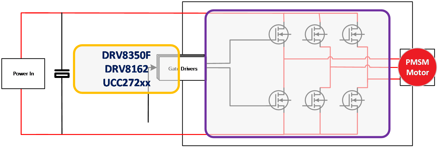 Figure 5 BLDC Gate Driver Diagram
There are many different situations which designers needs to analyze and define the requirements to optimize the motor drive systems for the humanoid robot. TI has designs which can solve all four categories of designs to enable designers to build humanoid robots.
Functional Safety
When planning for future designs, it is important to select devices that help simplify functional safety certification. Standards such as ISO13482, ISO10218, and the ISO 3691-4 provide insights to what to expect in the future for humanoid safety requirements. Both class C standards (ISO10218 and ISO3691-4) refer to ISO13849 stating that the system needs to be PLd, however, the ISO3691-4 leaves the architecture up to the implementer and the ISO10218 mandates a CAT3 architecture. Considering the worst-case scenario from these standards at least CAT3 PLd safety considerations must be taken for a humanoid robot. The safety architecture shown in needs to implement a CAT3 system.
To enable safety on a motor drive typically the standard IEC61800-5-2 or the standard IEC60204-1 using a STO or category 0,1,2 type function is being implemented to enable the safe stop function, this stop function is heavily dependent on the gate driver and how to disable the gate driver function. TI is working with TüV SüD to document concepts showing how to use TI gate drivers for this type of safety function. See Design Smaller Safe Torque Off (STO) Systems Using Integrated 3-Phase Smart Gate Drivers for more details.
TI offers many devices with extensive safety documentation to enable customers to build safety designs, see https://www.ti.com/technologies/functional-safety.html .
 Figure 6 Illustration from IEC13849-1:2015
Conclusion
When designing humanoid robot motor drivers, there are many types of drives with each type having different design specifications based on the function in the bot. TI has a broad portfolio of integrated circuits which enable customers to realize the different design specifications to build robots which can quickly react in the environment. Figure 7 shows a block diagram of a1kW to 1.9kW motor drive system which features multiple TI products.
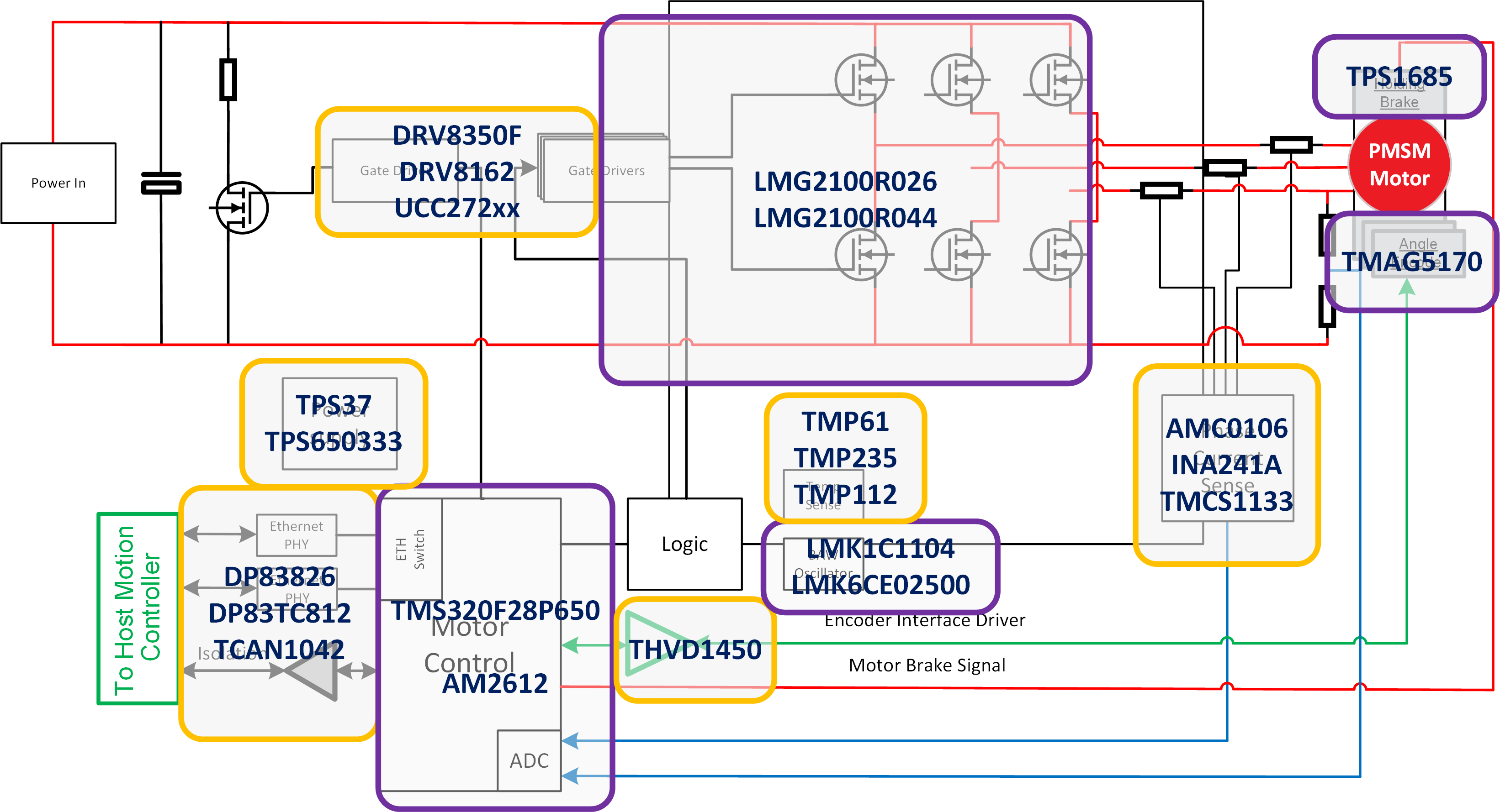 Figure 7 1kW to 1.9kW System Block Diagram
TI offers severals of evaluation modules and reference designs to help engineers evaluate system designs faster and streamline the process of building a production-ready design. TI also helps designers simplify and accelerate the functional safety system design process with functional safety products and design tools.