SLVUD94 September 2025 UCC27734 , UCC27734-Q1 , UCC27735 , UCC27735-Q1
5.3.1 Power Up
- Before beginning the power up test procedure, verify the connections with Figure 5-1.
- Enable supply #1, if the current on DMM1 is more than 0.20mA and less than 0.71mA, everything is set correctly.
- Enable function generator outputs channel-A and channel-B.
- The following conditions should be present:
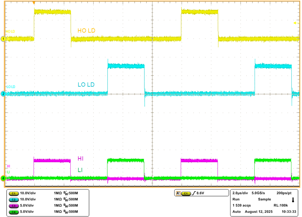
- Stable pulse output on channel-1 and channel-2 in the oscilloscope, refer to Figure 5-2
- Frequency measurement should be 100kHz, ±5kHz or equal to the programmed function generator frequency
- DMM #1 should display around 3.5mA, ±1mA with the default load capacitance of 1.0nF. For more information about operating current, refer to UCC2773x Data Sheet and UCC2773x-Q1 Data Sheet.
- Connect ENA_IN test point to GND test point with Jumper J1. The pulse outputs on channel-1 and channel-2 will cease operation and the voltage level should be near ground.
 Figure 5-2 Example Input and Output Waveforms (Green and Magenta are PWM Inputs, Yellow and Blue are Driver Outputs)