SCDA058 September 2025 TMUX1575 , TMUX4827 , TMUX7612 , TS5A22362 , TS5A22364
4 THD(+N) of Multiplexers
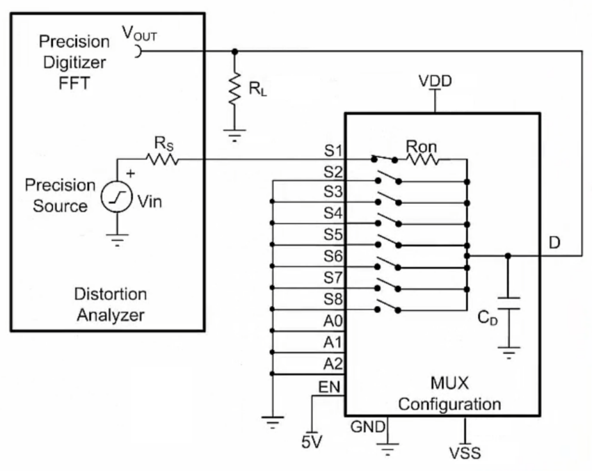
The THD + N test setup schematic for a multiplexer (MUX) device is shown in Figure 4-1. A low distortion sine wave source, Vin, is applied to the MUX channel under test S1 to D. The output signal, noise and harmonics are captured by a precision digitizer. This measurement is conducted over a range of Vin frequencies (for example, for audio applications, sweep is 20Hz to 20kHz), and the results are combined to form a plot of THD + N across frequency.
 Figure 4-1 Test Setup Schematic for Measuring Multiplexer THD+N