SLYW038D September 2014 – April 2025 AFE030 , AFE031 , AFE032 , ALM2402-Q1 , LMC6035-Q1 , LMV601 , LMV602 , LMV604 , LMV611 , LMV612 , LMV614 , LMV881 , OPA1602 , OPA1604 , OPA1612 , OPA1612-Q1 , OPA1622 , OPA1652 , OPA1654 , OPA1662 , OPA1662-Q1 , OPA1664 , OPA1688 , OPA170 , OPA170-EP , OPA171-Q1 , OPA172 , OPA180 , OPA188 , OPA191 , OPA192 , OPA197 , OPA211-EP , OPA2170 , OPA2171 , OPA2171-EP , OPA2171-Q1 , OPA2172 , OPA2180 , OPA2188 , OPA2192 , OPA2211-EP , OPA2211-HT , OPA2227-EP , OPA2277-EP , OPA2313 , OPA2314 , OPA2314-EP , OPA2314-Q1 , OPA2316 , OPA2317 , OPA2320-Q1 , OPA2322-Q1 , OPA2376-Q1 , OPA2625 , OPA313 , OPA314 , OPA316 , OPA317 , OPA320 , OPA322 , OPA348-Q1 , OPA355-Q1 , OPA4170 , OPA4171 , OPA4171-Q1 , OPA4172 , OPA4180 , OPA4188 , OPA4192 , OPA4277-EP , OPA4313 , OPA4314 , OPA4316 , OPA4317 , OPA4322 , OPA4322-Q1 , OPA549-HIREL , OPA564-Q1 , OPA625 , SM73307 , SM73308 , TLC2274-HT , TLE2141-Q1 , TLV2314 , TLV2316 , TLV2333 , TLV27L2-Q1 , TLV314 , TLV316 , TLV333 , TLV4314 , TLV4316 , TLV4333
- 1
- Analog Engineer's Pocket Reference
- Conversions
- Discrete Components
- Analog
-
Amplifier
- Basic op amp configurations
- Op amp bandwidth
- Full power bandwidth
- Large signal response (slew rate)
- Settling Time
- Combining noise sources
- AC response versus frequency (dominant 2-pole system)
- Stability open loop SPICE analysis
- Power dissipation calculation
- Electrical overstress (EOS) protection
- Notes
- PCB and Wire
-
Sensor
- Thermistor
- Resistive temperature detector (RTD)
- Diode equation vs. temperature
-
Thermocouple (J and K)
- Type J thermocouples translating temperature to voltage (ITS-90 standard)
- Type J thermocouples translating voltage to temperature (ITS-90 standard)
- Type K thermocouples translating temperature to voltage (ITS-90 standard)
- Type K thermocouples translating voltage to temperature (ITS-90 standard)
- Thermistor: Resistance to temperature, Steinhart-Hart equation
- Thermistor: Temperature to resistance, Steinhart-Hart equation
- Notes
- Digital
- ADC
- DAC
- Multiplexer
- TI Worldwide Technical Support
Inductor equations
Series inductors
Parallel inductors
Two parallel inductors
Where
Lt = equivalent total inductance
L1, L2, L3…LN = component inductance
Instantaneous voltage across an inductor
Where
v = instantaneous voltage across the inductor
L = inductance in henries (H)
= instantaneous rate of current change
Energy stored in an inductor
Where
E = energy stored in an inductor in joules (J)
I = current in amps
L = inductance in henries (H)
Equation for charging an RC circuit
General relationship
Where
VC = voltage across the capacitor at any instant in time (t)
VS = the source voltage charging the RC circuit
t = time in seconds
τ = RC, the time constant for charging and discharging capacitors
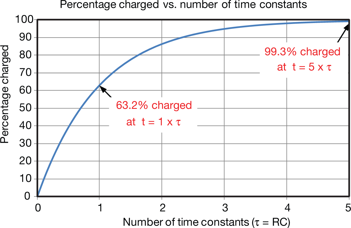
Graphing Equation 37 produces the capacitor charging curve below. Note that the capacitor is 99.3% charged at five time constants. It is common practice to consider this fully charged.
 Figure 13 RC charge curve
General Relationship
Where
VC = voltage across the capacitor at any instant in time (t)
Vi = the initial voltage of the capacitor at t = 0s
t = time in seconds
τ = RC, the time constant for charging and discharging capacitors
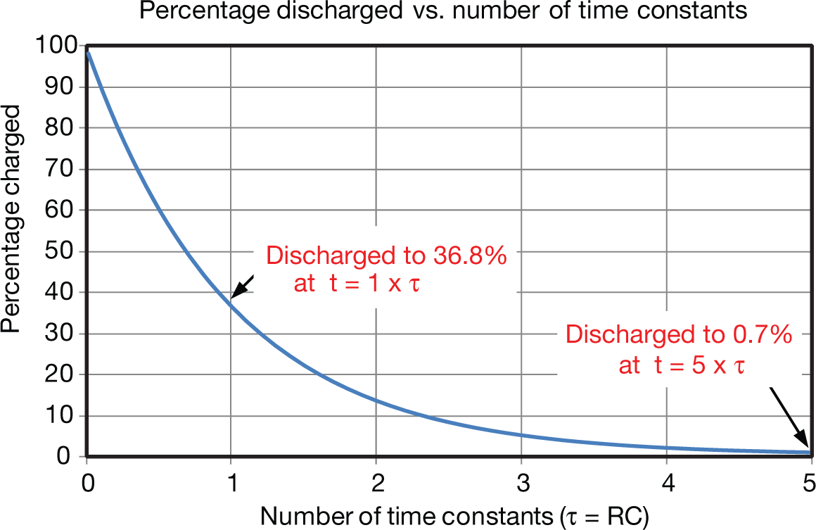
Graphing Equation 39 produces the capacitor discharge curve below. Note that the capacitor is discharged to 0.7% at five time constants. It is common practice to consider this fully discharged.
 Figure 14 RC discharge curve
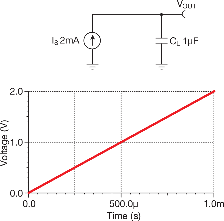
Capacitor with constant current source
 Figure 15 Capacitor with constant
current source
Figure 15 Capacitor with constant
current sourceGeneral equation for capacitor voltage current
For constant current
Where
IS = constant current source in amps (A)
VOUT = voltage developed across the capacitor in volts (V)
CL = load capacitance in farads (F)
t = time in seconds (s)