SLYW038D September 2014 – April 2025 AFE030 , AFE031 , AFE032 , ALM2402-Q1 , LMC6035-Q1 , LMV601 , LMV602 , LMV604 , LMV611 , LMV612 , LMV614 , LMV881 , OPA1602 , OPA1604 , OPA1612 , OPA1612-Q1 , OPA1622 , OPA1652 , OPA1654 , OPA1662 , OPA1662-Q1 , OPA1664 , OPA1688 , OPA170 , OPA170-EP , OPA171-Q1 , OPA172 , OPA180 , OPA188 , OPA191 , OPA192 , OPA197 , OPA211-EP , OPA2170 , OPA2171 , OPA2171-EP , OPA2171-Q1 , OPA2172 , OPA2180 , OPA2188 , OPA2192 , OPA2211-EP , OPA2211-HT , OPA2227-EP , OPA2277-EP , OPA2313 , OPA2314 , OPA2314-EP , OPA2314-Q1 , OPA2316 , OPA2317 , OPA2320-Q1 , OPA2322-Q1 , OPA2376-Q1 , OPA2625 , OPA313 , OPA314 , OPA316 , OPA317 , OPA320 , OPA322 , OPA348-Q1 , OPA355-Q1 , OPA4170 , OPA4171 , OPA4171-Q1 , OPA4172 , OPA4180 , OPA4188 , OPA4192 , OPA4277-EP , OPA4313 , OPA4314 , OPA4316 , OPA4317 , OPA4322 , OPA4322-Q1 , OPA549-HIREL , OPA564-Q1 , OPA625 , SM73307 , SM73308 , TLC2274-HT , TLE2141-Q1 , TLV2314 , TLV2316 , TLV2333 , TLV27L2-Q1 , TLV314 , TLV316 , TLV333 , TLV4314 , TLV4316 , TLV4333
- 1
- Analog Engineer's Pocket Reference
- Conversions
- Discrete Components
- Analog
-
Amplifier
- Basic op amp configurations
- Op amp bandwidth
- Full power bandwidth
- Large signal response (slew rate)
- Settling Time
- Combining noise sources
- AC response versus frequency (dominant 2-pole system)
- Stability open loop SPICE analysis
- Power dissipation calculation
- Electrical overstress (EOS) protection
- Notes
- PCB and Wire
-
Sensor
- Thermistor
- Resistive temperature detector (RTD)
- Diode equation vs. temperature
-
Thermocouple (J and K)
- Type J thermocouples translating temperature to voltage (ITS-90 standard)
- Type J thermocouples translating voltage to temperature (ITS-90 standard)
- Type K thermocouples translating temperature to voltage (ITS-90 standard)
- Type K thermocouples translating voltage to temperature (ITS-90 standard)
- Thermistor: Resistance to temperature, Steinhart-Hart equation
- Thermistor: Temperature to resistance, Steinhart-Hart equation
- Notes
- Digital
- ADC
- DAC
- Multiplexer
- TI Worldwide Technical Support
Stability open loop SPICE analysis
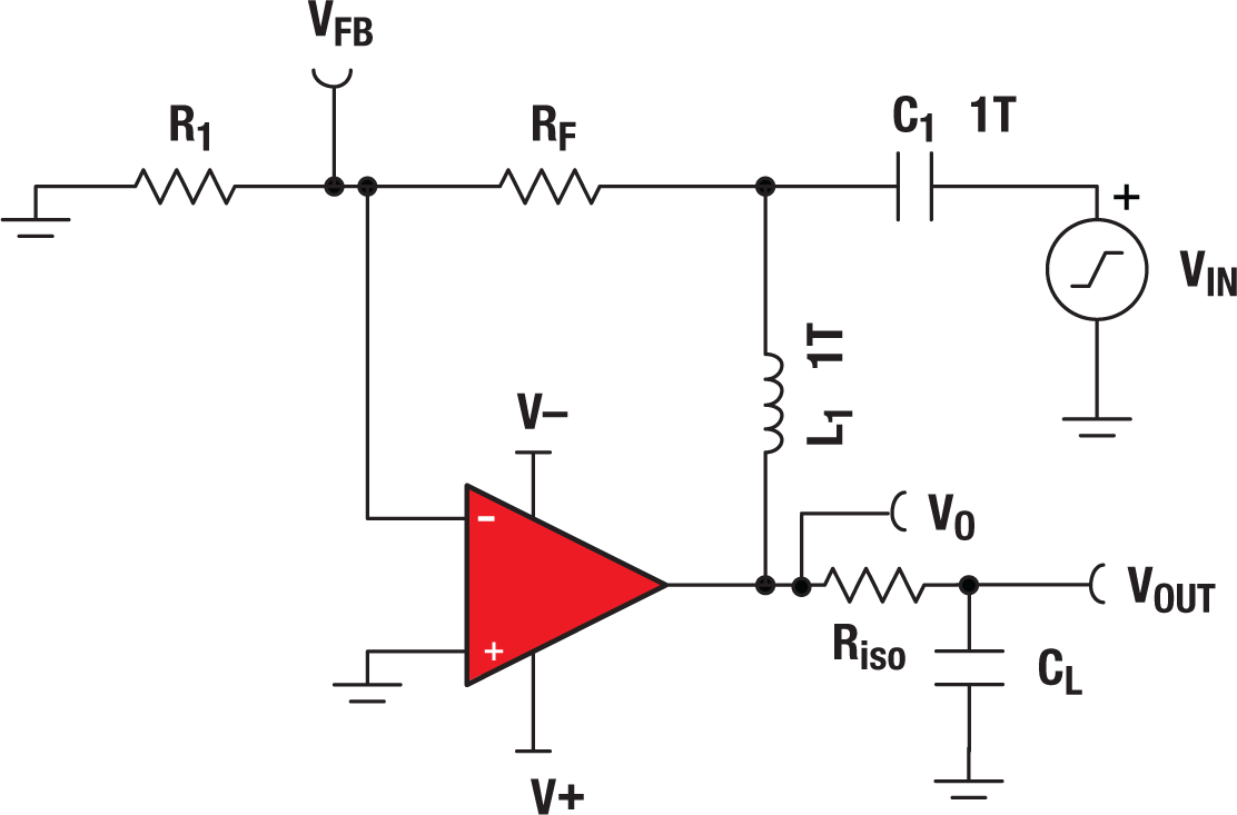
 Figure 51 Common spice test circuit used for stability
Loaded open-loop gain
Feedback factor
Closed-loop noise gain
Loop gain
Where
VO = the voltage at the output of the op amp
VOUT = the voltage output delivered to the load, which may be important to the application but is not considered in stability analysis
VFB = feedback voltage
RF, R1, RiS0 and CL = the op amp feedback network and load. Other op amp topologies will have different feedback networks; however, the test circuit will be the same for most cases. Figure 50 shows the exception to the rule (multiple feedback).
C1 and L1 = components that facilitate SPICE analysis. They are large (1TF, 1TH) to make the circuit closed-loop for DC, but open loop for AC frequencies. SPICE requires closed-loop operation at DC for convergence.
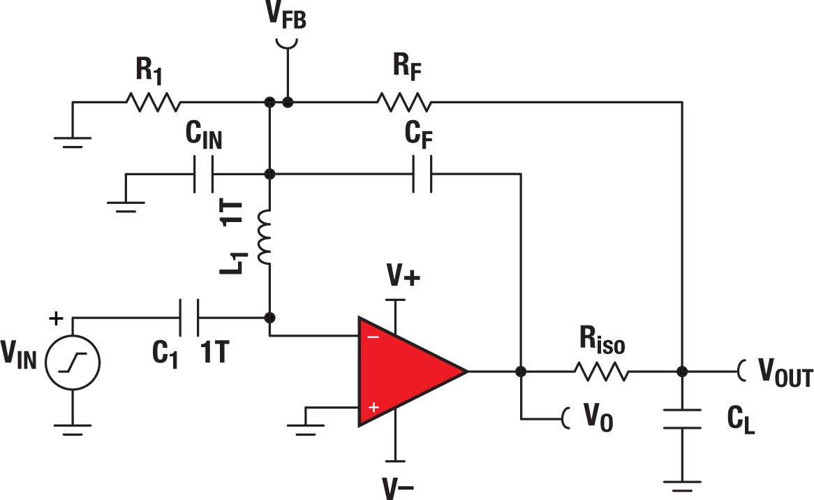
 Figure 52 Alternative (multiple feedback) SPICE test circuit used for stability
Loaded open loop gain
Feedback factor
Closed-loop noise gain
Loop gain
Where
VO = the voltage at the output of the op amp
VOUT = the voltage output delivered to the load. This may be important to the application but is not considered in stability analysis.
VFB = feedback voltage
RF, R1, Riso and CF = the op amp feedback network. Because there are two paths for feedback, the loop is broken at the input.
C1 and L1 = components that facilitate SPICE analysis. They are large (1TF, 1TH) to make the circuit closed loop for DC, but open loop for AC frequencies. SPICE requires closed-loop operation at DC for convergence.
CIN = the equivalent input capacitance taken from the op amp datasheet. This capacitance normally does not need to be added because the model includes it. However, when using this simulation method the capacitance is isolated by the 1TH inductor.